
Græy & Orange
Robosub 2020
We enhanced 2019's Autonomous Underwater Vehicle (AUV) Orange and created Græy to compete in RoboSub's 2020 challenge: 23 Skidoo.
-
Ranked 1st out of 33 teams in Technical Design Report
-
Ranked 1st out of 33 teams in Website
-
Ranked 2nd out of 33 teams in Video
-
Ranked 1st out of 33 teams in Overall Performance
Ranked #1

System Overview
This year we mainly focused on improving our AUV’s navigation and expanding our mission capability. We designed Græy to be our primary AUV which we created with all of our lessons learned. We updated Orange so it could be the secondary AUV and added modem so it can communicate with Græy. In making Græy, we learned how to use Robot Operating System (ROS), design Printed Circuit Boards (PCBs), machine learning, hydrophones, intersub communication, and Solid Works. We continued using the systems engineering process and parallel prototyping as they both served us well last year. To deal with the COVID-19 pandemic that occurred during the season, our team followed stay-at-home orders and communicated through bi-weekly team video conferences and multiple inter-subteam calls.
Since our AUVs must run autonomously, they have multiple sensors and programs to navigate and control their movement. This year we used sonars, hydrophones, cameras, modems, and a Doppler Velocity Log (DVL). This way we can detect missions or obstacles around the robot, locate the missions, communicate between the subs, and know our exact location in the pool so we can navigate accurately.
Græy
Our primary sub, Græy, can attempt every mission in the 2020 RoboSub competition! It is equipped with a DVL, modem, sonar, 2 cameras, 3 hydrophones, and a gripper.
Orange
We added a modem to Orange so it can communicate with Græy to do the intersub communication task. To save money, it does not have a DVL, but can incorporate Græy's DVL if needed should Græy stop working. It also serves as a backup sub with the capability to do most missions.
Competition Strategy
Last year, we aimed to be in the top half and exceeded our expectations by ranking 12th overall and 3rd in static judging. The systems engineering process and K.I.S.S. (keep it simple, silly) worked for us, so we continued following those practices and added the Agile process. We continued to use Commercial Off The Shelf products, and design custom hardware and software to supplement as needed. Last year we used the MAVLink software framework. Now, we use ROS for interprocess communication. With ROS, we can now properly integrate input from multiple sensors. To enhance navigation accuracy, we added a DVL and hydrophone capabilities. CV is used to identify the buoys and differentiate whether the tasks correspond to the G-man or Bootlegger. We enhanced our vision capabilities by focusing on determining the position of the image in relation to the AUV. Hydrophones are used to triangulate the pingers that mark the torpedoes and surfacing tasks. A DVL is used to navigate close to the target so the sonar and CV can be more effective to accomplish the task. We use multiple sensors for navigation as fail-safes to minimize the impact of individual sensor failure. Additionally, each sensor, like the DVL, has its own internal error correction and filters.

This overhead map of the competition field depicts Græy and Orange's operating zones which are marked by the dotted green line and orange line, respectively.
We emulated Orange’s simple and modular construction when designing Græy. The design allows easy expansion by simply increasing the cylinder length and diameter, accommodating for the increased amount of electrical components and the additional ports for the added equipment. We decided to compete with two AUVs because of the strategic advantages in the rules as only the highest points earned at each attempted task will be counted and each run is ended once both AUVs have surfaced. We can also gain points through the intersub communication task. The point benefits of two AUVs far outweigh the cons presented in having weight penalties.
Mechanical
This year, we built the mechanical system from our lessons learned from last year’s AUV. We focused on expanding the capabilities for our sub by increasing the number of penetrator ports to allow for more capabilities while maintaining our same 24 in by 23 in by 13 in dimensions form last year. This allowed our team to comfortably fit within the size and weight requirements of this year’s competition. We used laser cut delrin instead of our PLA 3D printed components for the larger components to increase durability and longevity of our AUV. We combined this 2D construction with our smaller in house 3D printed parts to mount nearly all components onto our frame.
Electronics Enclosure
For the electronics enclosure, we knew we had to increase the volume of the enclosure and the surface area of the electronics boards inside to accommodate for the new sensors and electronics components and the ports they needed on the end cap. We experimented with a few different designs including a triangular folding board we saw last year. It was fun but we went back to a simple design since our board served as a holding plate vs an integrated circuit card. After settling on a design we started incorporating as much detail as we could. This was so that we could learn to make CAD models more precise, and also so that we could have a very clear image of how the electronics enclosure would look. When building the sub, we were able to construct the electronics enclosure more efficiently because of the amount of detail in the CAD.
Electronics Board
For the electronics board, the team wanted to challenge our designing capabilities. Last year we saw a team which made a foldable electronics board that was able to transform from a triangular prism to a flat plane. We tried this design in CAD but ultimately stayed with our more simple tiered design. The frame and enclosure holder designs were changed from additive manufacturing to subtractive manufacturing as our MJF sponsor is not available right now. Consequently, our designs now use stacked laser cut plates.
Flow Sensor
This year we tried to make a flow meter as a substitute for a DVL because DVLs are very expensive. However, after receiving input from the RoboSub forums, we realized there is no way that we know of to distinguish between the current in the pool and the displacement of the water from the robot.
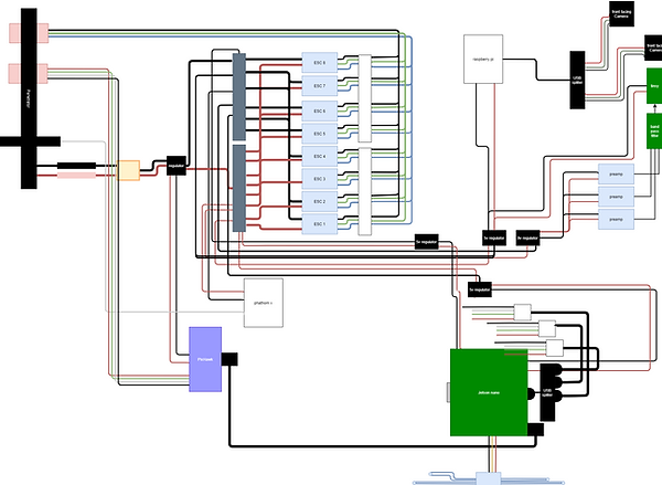
Electrical
At the beginning of our season, the electrical team laid out a list of changes that we needed to make after last season. Since we were a rookie team, our team utilized the BlueRov electronics enclosure, which came with the kit, as it was the easiest and quickest way to produce a successful electronics board. The downside to this is that our electronics lacked customization to perfectly suit our teams needs. Therefore, the electrical team reached out to all of the team members to gather requirements before we planned our layout.
Kill Switch
In developing the killswitch, we outlined the issues with last year’s design — accuracy and efficiency. Our previous design was a magnetic switch that would interrupt the software with a background script. The switch faced latency when pulled. Overall, the design was inefficient and potentially dangerous to the AUV and divers. To design a better switch that would be both accurate and efficient, we found it best to contact teams we competed alongside with last year. After performing trade studies and researching other teams’ methods, we wanted to go with a MOSFET killswitch since it stood out as the most efficient and effective design. This switch would mechanically disconnect with the robot so we would not face a programming error. But, time permitted us to go with a more testable design. This is where our team went through a second iteration and decided to pursue a magnetic limit switch. The switch would communicate and cut current flow throughout the design when the magnetic fields were removed.
Power Distribution Board
We also collaborated with electrical engineering students from the University of California San Diego (UCSD) to create a custom Power Distribution Board which replaces the exposed terminals we previously used. Though it takes up more surface area it reduces the amount of wires, consolidates the connection points and shields the terminals.
Payloads
Torpedoes
We continued to develop a torpedoes system. Last year we tried a self-propelled system. This year we tried a pneumatic system. We are still developing the torpedoes. See the torpedoes evolution document to track our progress.
Gripper
To manipulate the objects on the field, we integrated the Newton Subsea Gripper from Blue Robotics that we bought last year.
Modems
To do intersub communication, we decided to learn from a proven and reliable system first as a base so we bought a set of modems from Water Linked to experiment with. See the modem evolution document to track our progress.
Software
Architecture
Issuing Commands / Basic Robot Translation (MAVLink)
Orange and Græy’s thrusters are controlled by a flight controller known as the “PixHawk”. The PixHawk runs a firmware known as “ArduSub.” The flight controller receives commands from a single board computer (the Jetson Nano) via a communication protocol called Micro Air Vehicle Link (MAVLink). MAVLink commands can be issued from programs via libraries such as pymavlink (a Python implementation of MAVLink).
Basic translation is handled by the flight controller, meaning that if we wish the AUV to move in a certain direction, we simply need to send a command to the flight controller with the specified direction and power. The details concerning which motors should be activated to translate in the specified direction (forward/backward, laterally, yaw, vertically, etc) are handled by the flight controller. We also take advantage of the flight controller’s capability to maintain a depth while translating forwards, backwards, and laterally.
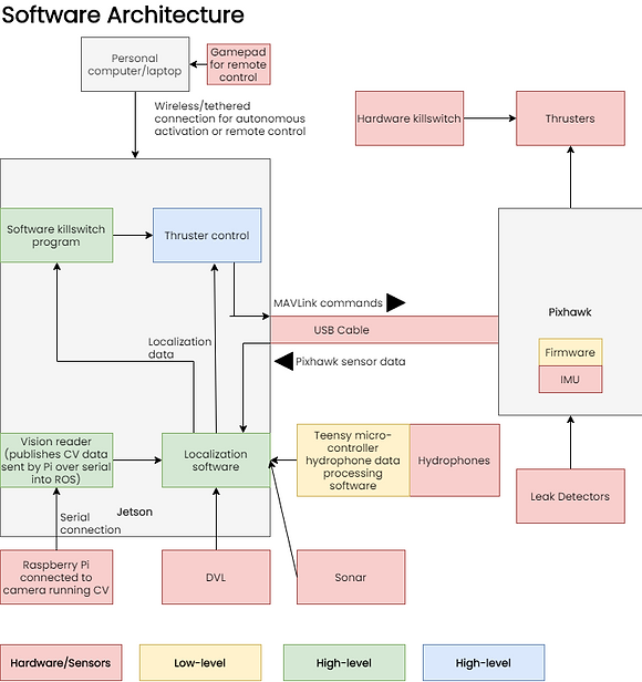
Software Architecture and ROS
Our software system builds on top of the flight controller’s functionality that we mentioned in the previous section. Our software system, which is split across multiple programs (processes), is structured below:

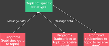
The processes communicate with each other using Robot Operating System (ROS), a robotics middleware that, among other things, allows for inter-process communication. Inter-process communication under ROS operates via a publisher-subscriber model, in which the senders of the message does not send it to a specific receiver, but rather a “topic” which any other process can read from if they wish. Although the architecture diagram above makes it appear as if data is being sent from one specific process to another, in reality it is more like this:
Every program in our software system has its own specific task to complete, transforming one kind of data into another kind of data, such as the computer vision programs, which take image data and converts it to data that can be used to determine robot position. The function of each program shown in the software architecture diagram is explored in greater detail in the following sections.
Localization
Last year, our robot navigated in the field using a compass and time-based model, which meant that we did not necessarily know our position in the pool. Hence, a goal of ours for this year was to be able to understand our position at any given time. Since we have an integrated computer vision process, a process that tracks position using a Doppler Velocity Log, a compass/imu, barometer, and other sensors, we have the capability to determine our position using feedback from multiple different sources.


Hydrophones
To help with navigating to the torpedoes and surfacing missions we researched how to use hydrophones to determine direction and distance away from a pinger/sound source. We used three hydrophones and triangulation this year to figure out the direction the pinger is located in. We will continue to refine our program and attempt to be able to calculate distance next year.
Computer Vision
Last season, we were unable to use any vision systems due to lack of integration. This year, we focused heavily on vision, with three main objectives: Vuforia, OpenCV, and Neural Networks. All three methods were used for object recognition this season.
Vuforia: Our team has participated in FIRST Tech Challenge, which introduced us to Vuforia, a CV library used to recognize images. Taking into account the increase in images for this year’s missions, we decided to try to use this to detect images and determine AUVs position relative to them. We started by prototyping on an Android phone as this was the platform we had previously used and we could not run on our Jetson Nano with Vuforia; Vuforia is unsupported on Linux. After testing with the phone in our electronics enclosure, we decided to switch to a Single-Board Computer (SBC) so we would be able to easily integrate into our AUVs. We chose to use a Raspberry Pi running Android. On the Raspberry Pi, we had to make modifications to our code’s hardware maps and event loops in order to ensure the system would be able to work inside the enclosure, using Græy’s camera. After modifications, Vuforia now gives us the capability to retrieve roll, pitch, yaw, x, y, z coordinate values.
Open Computer Vision (OpenCV): In our first season of RoboSub (2019), our team dived into the world of computer vision. Using OpenCV, we made a program to detect the orange gate. However, due to the fact that computer vision was not integrated into our competition strategy, we were not able to utilize our computer vision program in the competition environment. This year, we integrated computer vision into our competition strategy, which allowed for a smooth integration of computer vision into our competition robot. We utilized a common CV program, consisting of filters such as color isolation, gaussian blur, erosions, dilations, bounding boxes, and many other algorithms to enhance image quality. We were able to recycle the same program for all missions, by simply changing the Hue Saturation Value (HSV). For the buoy mission, we also utilized saliency detection. We experimented with filters such as histogram equalization, dark channel, and closing. We developed not only mission detection programs, but also an angle detection program to provide the navigation team with reliable pan-angle and distance detection. By observing the distortion of the detected object, this program can calculate the angle between the sub's camera and the task in front of it. Through vigorous testing, we were able to calculate angle with a ±5 degree of accuracy. We are currently working on using advanced filters such as the Kalman filter to assist navigation. Along with filters, we learned how to integrate our own algorithms into our code to create repeatable programs for navigation to utilize. Examples of repeatable programs are distance and pan angle detection, 2 programs that serve as options for Græy through the voting algorithm.

Neural Networks: This season, we utilized artificial neural networks (ANNs). We did this mostly for learning purposes, due to the fact that our team was familiar with OpenCV, making ANN’s our next step in the vision subteam. Because Machine Learning was a completely new concept to us, we read through many books, such as Deep Learning for Computer Vision, by Adrien Rosebrock. We then got to data collection, which consisted of splitting videos of the gate, taken last season, into multiple frames. By doing this, we were able to get thousands of data points in a matter of minutes. We experimented with different types of networks, including K-Nearest Neighbors and Recurrent Neural Networks, but came to the conclusion that Convolutional Neural Networks (CNNs) would be the best option, as they are made for image recognition and would give us the highest accuracy.
We captured around 2,400 images, which were split evenly into training and testing data. Because of our lack of data in time, we were only able to achieve a validation accuracy of around 70 percent (although our model accuracy was closer to 80 percent). Originally, we failed to use a shuffling method, which made our results seem better than they actually were, however we ended up using a numpy shuffling function to train our data more accurately.
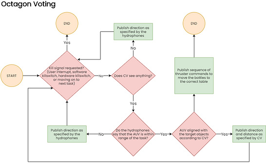
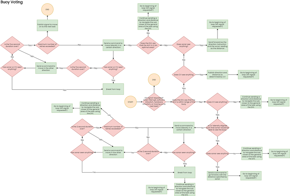
Voting
As covered by the previous section, our AUVs have many sources of localization information. A continuously running process uses the DVL to calculate the displacement of the AUV from the origin. Computer vision is used to calculate the sub’s position relative to the missions. Hydrophones are used to calculate the angle between the robot and the pinger, and other sensors are used as input. However, none of these sources of information can be trusted to work correctly all the time, which is the reason that we utilize a “voting” process to determine which sensors are appropriate at which time. If computer vision sees something but the DVL says that the robot is not within visible range of a mission, the DVL’s results are cross referenced with hydrophone and compass data to determine which one is correct. It uses this information to determine a singular position and heading on a coordinate grid that it deems is the best estimate. This is sent to the thruster command process.

Thruster Command
The Thruster Command process is the program that is responsible for moving the robot. As mentioned in the “Architecture” section, MAVLink commands can be sent from programs to the flight controller, for basic translation. The thruster command process builds on top of this, by using the robot’s current position to have the capability to navigate to any specified coordinate point in the mission area. It does so by calculating the angle between the current and destination positions and turning to that heading, then going forward towards that position while constantly correcting heading, until the current position equals the destination position.
This flowchart moves the AUV from one position to another. It does so by turning to the target and driving forward. To ensure the AUV stays on course, we constantly correct our heading, which is calculated in the bottom flowchart, to point towards our target. Once we're within 10cm of the target, the process ends.


We calculate our target position using an inverse tangent function, given the difference in x and y.
Simulation
Testing is always important to our team. With COVID-19, we were limited in our ability to meet and test in-person. We distributed equipment to team members and utilized family members to assist with testing at home. We set up an environment to collaborate and test remotely resulting in parallel development without disruption. We tested AUV movement on virtual simulations, CV systems on last year videos, and the hydrophones and flight controller on benchtop setups. We integrated different subsystems in Computer Aided Design (CAD), and simulation modeling. We learned how to write detailed Interface Control Documents (ICDs) and established more frequent reviews to ensure clear communication.
In Pool Testing
This year, since we were unable to physically meet and test our subs in person, we decided to distribute our BlueROV2 and Orange between our teammates who had pools at their homes. We set up remote access abilities to the topside computer so that the programming team was able to control the vehicle without physically being near a pool. Through our in-pool testing, we were able to develop programs to bring the sub to a certain depth and also set up ROS on Orange.
Along this testing journey, we learned many valuable lessons. We learned to always take extra precautions when handling the sub such as tightening the end-cap or making sure there was no air seeping of the tubes, whether it was on land or in the pool. We also learned to install prerequisite software on one’s own hardware first, before attempting to do it on an AUV over a remote connection. We wasted a lot of time attempting to compile ROS on a Raspberry Pi on the BlueROV2, by sending instructions for commands to enter over a call; after spending a lot of time troubleshooting, we decided to try it on one’s own Raspberry Pi. During this phase, we found out that ROS and the other prerequisite ROS packages do not work on Raspbian.
RoboSub, RoboSub 2021, Grey, Orange, Simmulation, Torpedos, Gripper, Enclosure, Electronics